Search
Aerospace
Aerospace Vehicle Entry Flightpath Control
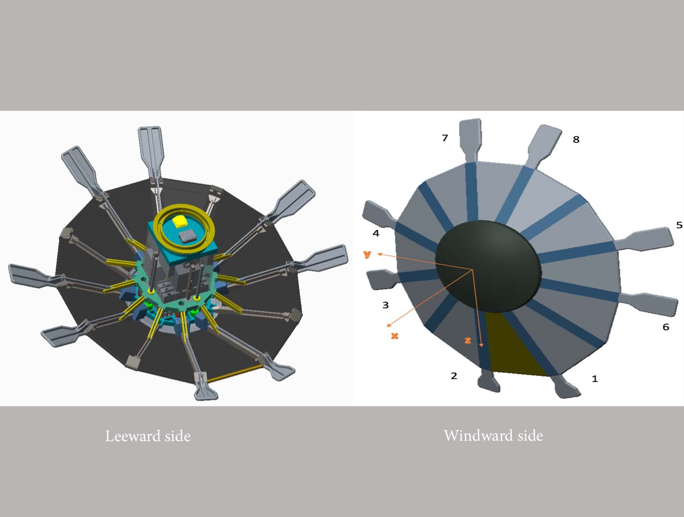
This novel flightpath control system exploits the dihedral effect to control the bank angle of the vehicle by modulating sideslip (Figure 1). Exploiting the dihedral effect, in combination with significant aerodynamic forces, enables faster bank accelerations than could be practically achieved through typical control strategies, enhancing vehicle maneuverability. This approach enables vehicle designs with fewer control actuators since roll-specific actuators are not required to regulate bank angle. The proposed control method has been studied with three actuator systems (figure below), Flaps Control System (FCS); Mass Movement Control System (MMCS); and Reaction Control System (RCS).
• FCS consists of a flap configuration with longitudinal flaps for independent pitch control, and lateral flaps generating yaw moments. The flaps are mounted to the shoulder of the vehicle’s deployable rib structure. Additionally, the flaps are commanded and controlled to rotate into or out of the flow. This creates changes in the vehicle’s aerodynamics to maneuver the vehicle without the use of thrusters.
• MMCS consists of moveable masses that are mounted to several ribs of the DEV heatshield, steering the vehicle by shifting the vehicle’s Center of Mass (CoM). Shifting the vehicle’s CoM adjusts the moment arms of the forces on the vehicle and changes the pitch and yaw moments to control the vehicle’s flightpath.
• RCS thrusters are mounted to four ribs of the open-back DEV heatshield structure to provide efficient bank angle control of the vehicle by changing the vehicle’s roll. Combining rib-mounted RCS thrusters with a Deployable Entry Vehicle (DEV) is expected to provide greater downmass capability than a rigid capsule sized for the same launch
Aerospace
eVTOL UAS with Lunar Lander Trajectory
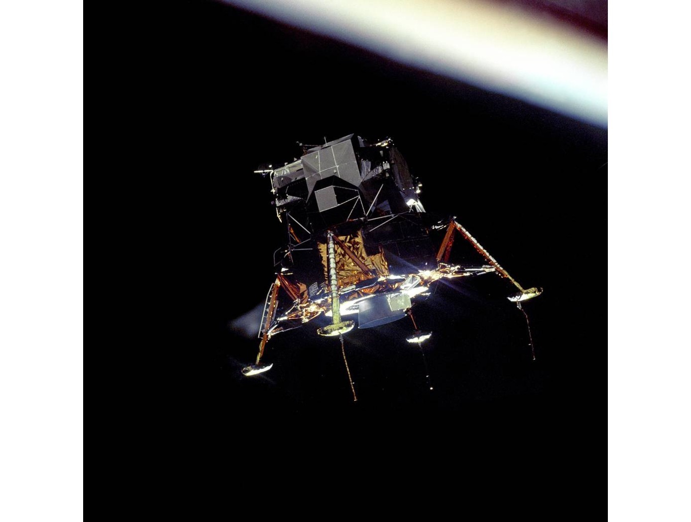
This NASA-developed eVTOL UAS is a purpose-built, electric, reusable aircraft with rotor/propeller thrust only, designed to fly trajectories with high similarity to those flown by lunar landers. The vehicle has the unique capability to transition into wing borne flight to simulate the cross-range, horizontal approaches of lunar landers. During transition to wing borne flight, the initial transition favors a traditional airplane configuration with the propellers in the front and smaller surfaces in the rear, allowing the vehicle to reach high speeds. However, after achieving wing borne flight, the vehicle can transition to wing borne flight in the opposite (canard) direction. During this mode of operation, the vehicle is controllable, and the propellers can be powered or unpowered.
This NASA invention also has the capability to decelerate rapidly during the descent phase (also to simulate lunar lander trajectories). Such rapid deceleration will be required to reduce vehicle velocity in order to turn propellers back on without stalling the blades or catching the propeller vortex. The UAS also has the option of using variable pitch blades which can contribute to the overall controllability of the aircraft and reduce the likelihood of stalling the blades during the deceleration phase.
In addition to testing EDL sensors and precision landing payloads, NASA’s innovative eVTOL UAS could be used in applications where fast, precise, and stealthy delivery of payloads to specific ground locations is required, including military applications. This concept of operations could entail deploying the UAS from a larger aircraft.
Information Technology and Software
Unique Datapath Architecture Yields Real-Time Computing
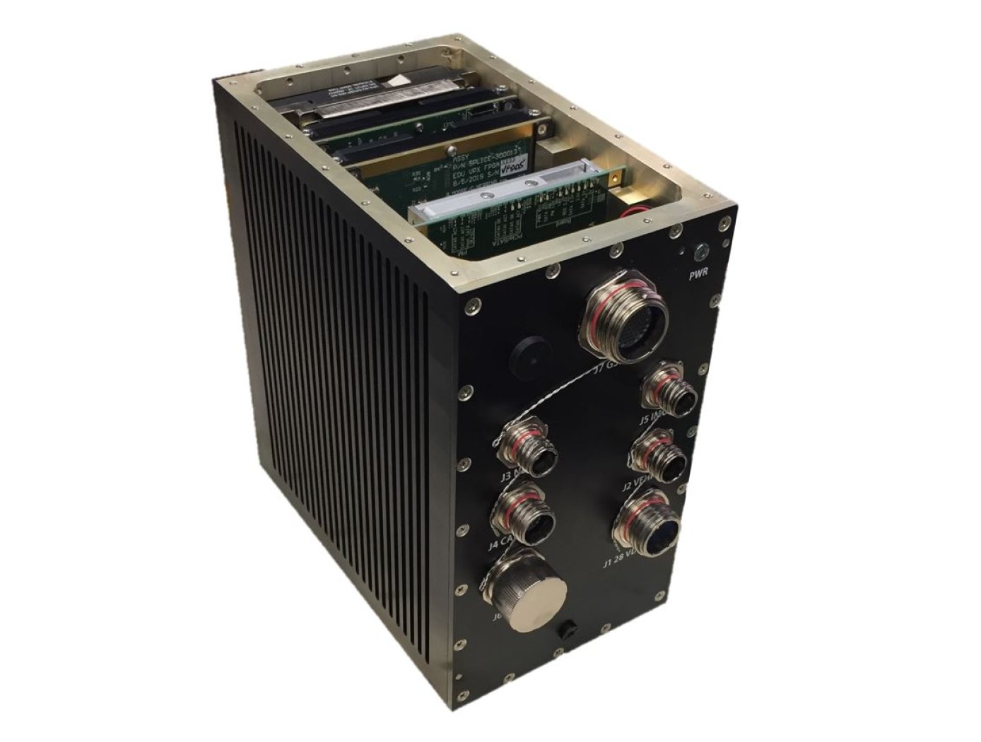
The DLC platform is composed of three key components: a NASA-designed field programmable gate array (FPGA) board, a NASA-designed multiprocessor on-a-chip (MPSoC) board, and a proprietary datapath that links the boards to available inputs and outputs to enable high-bandwidth data collection and processing.
The inertial measurement unit (IMU), camera, Navigation Doppler Lidar (NDL), and Hazard Detection Lidar (HDL) navigation sensors (depicted in the diagram below) are connected to the DLC’s FPGA board. The datapath on this board consists of high-speed serial interfaces for each sensor, which accept the sensor data as input and converts the output to an AXI stream format. The sensor streams are multiplexed into an AXI stream which is then formatted for input to a XAUI high speed serial interface. This interface sends the data to the MPSoC Board, where it is converted back from the XAUI format to a combined AXI stream, and demultiplexed back into individual sensor AXI streams. These AXI streams are then inputted into respective DMA interfaces that provide an interface to the DDRAM on the MPSoC board. This architecture enables real-time high-bandwidth data collection and processing by preserving the MPSoC’s full ability.
This sensor datapath architecture may have other potential applications in aerospace and defense, transportation (e.g., autonomous driving), medical, research, and automation/control markets where it could serve as a key component in a high-performance computing platform and/or critical embedded system for integrating, processing, and analyzing large volumes of data in real-time.

